 |
|||
|
|
|||
|
|
|||
| ||||||||||
|
| 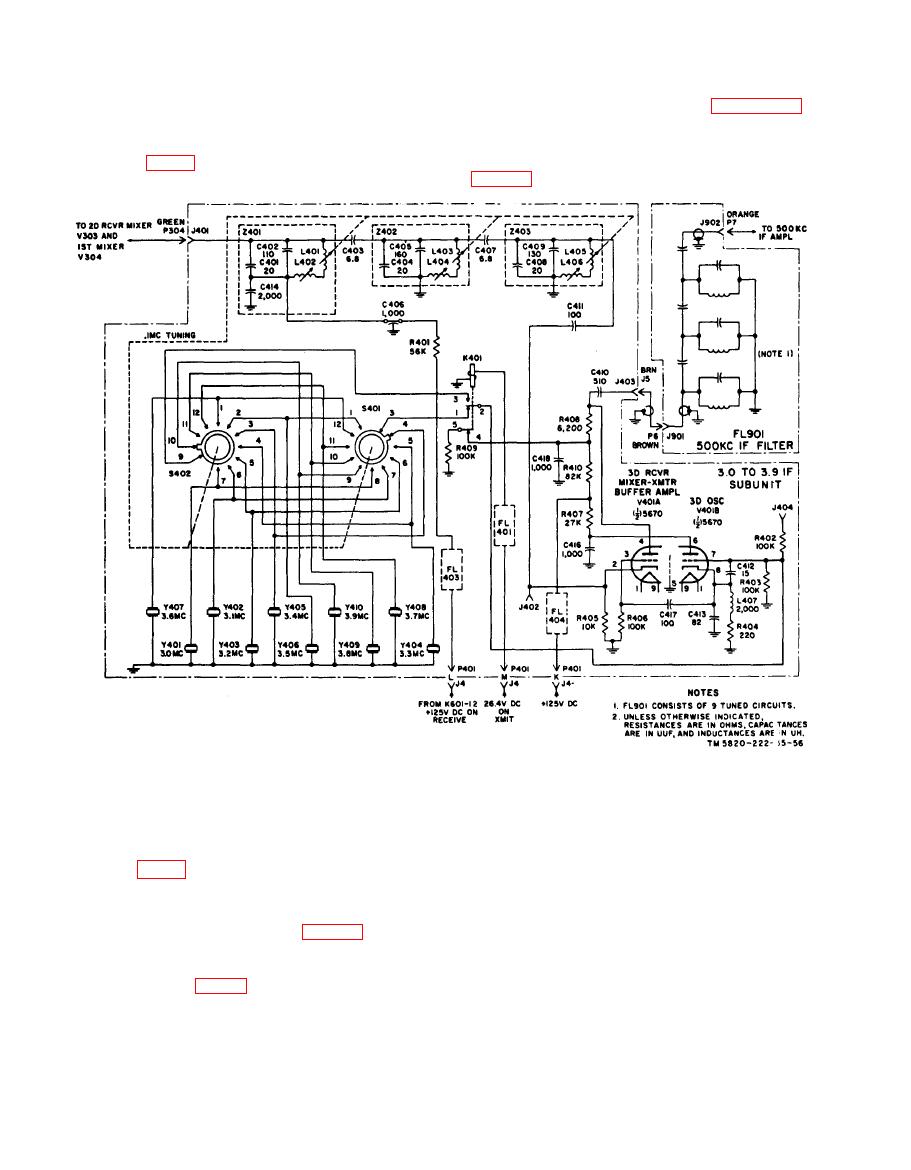 p a r a l l e l - t u n e d circuits in cascade and
from bandpass filters Z401, Z402, and
c a p a c i t i v e l y coupled. Only three of the
Z403. Jack J402 is a test point for mesaur-
t u n e d circuits are shown in figure 10.
ing the dc bias and rf voltage on the grid of
The 500-kc if signal is coupled from
V401A.
third receiver mixer V401A through
F L 9 0 1 to first 500-kc if. amplifier V501
(para 34).
T h e 500-kc if. filter consists of nine
Section VI. 500-KC IF. AND AUDIO AMPLIFIER SUBUNIT
J503 is provided for injecting a test signal
f o r troubleshooting. The control grid is
connected to the if. avc bus through isolat-
a. First 500-kc amplifier V501 is the
ing resistor R501. Resistor R502 provides
f i r s t of three if. amplifiers that amplify
cathode bias for V501 and capacitor C507
the 500-kc output of V401A (para 32). When
is a bypass capacitor to ground. Capacitor
this equipment is used for receiving, the
C504 provides a low-impedance path for rf
500-kc third if. is fed from 500-kc if.
signals from the screen grid to the cathode.
filter FL901 (fig. 10) through plug P8 and
b. Plate voltage is supplied from the
jack J502 to the control grid V501. Jack
|
|
Privacy Statement - Press Release - Copyright Information. - Contact Us |
