 |
|||
|
|
|||
|
|
|||
| ||||||||||
|
| 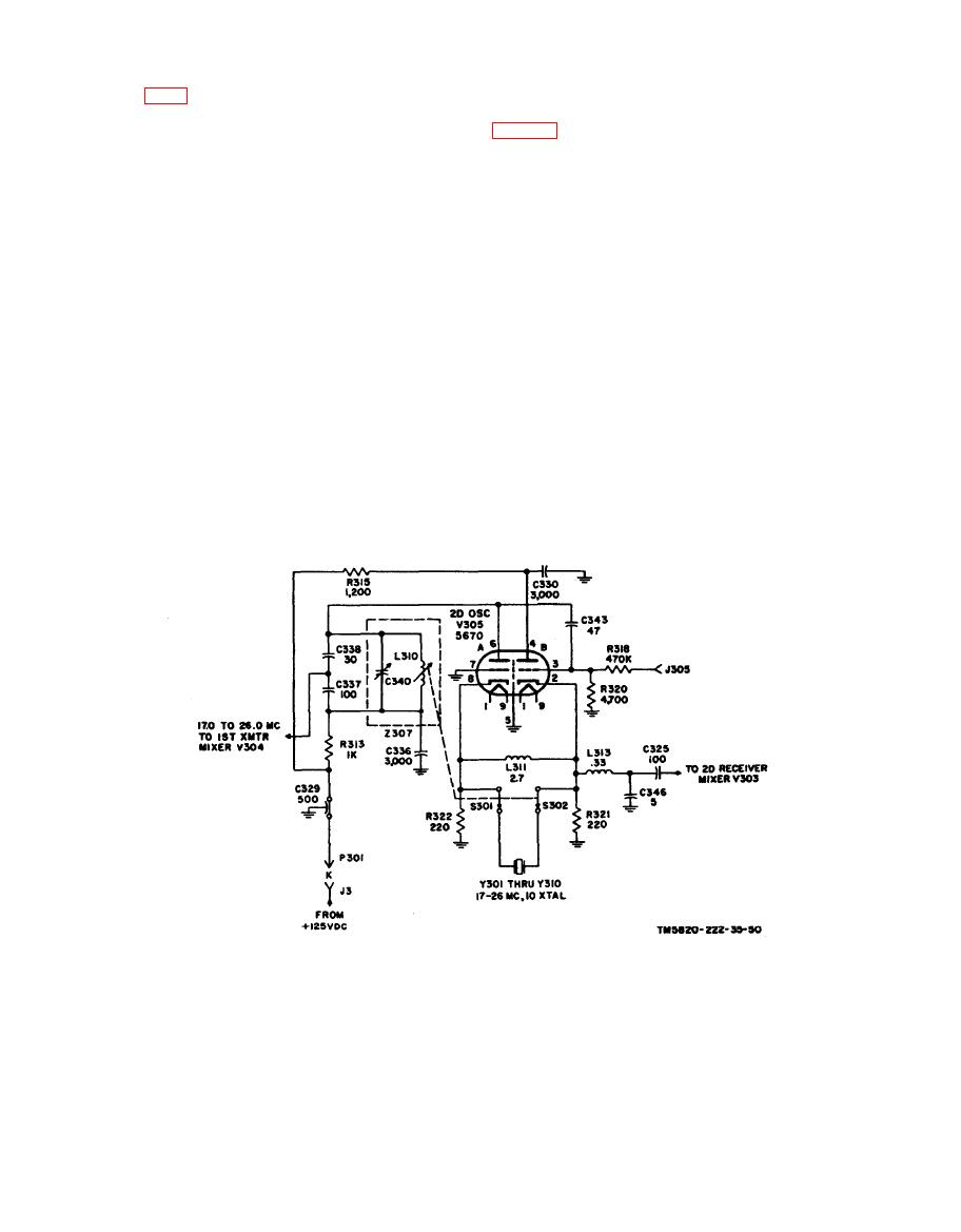 is coupled from the cathode of V305B to the
c a t h o d e of second receiver mixer V303
a. Second oscillator V305 is a cathode-
coupled, crystal-controlled oscillator. The
that consists of coil L313, capacitor C346,
grounded grid amplifier section (pins 6, 7,
and coupling capacitor C325. Rf choke L311
and 8) develops an output voltage across
n e u t r a l i z e s the crystal socket capacity.
parallel-tuned circuit 2307 which
Resistors R321 and R322 provide the cou-
functions as the plate load for V305A. Ca-
pling impedance at the cathodes of V305
pacitor C343 couples the output from the
and provide cathode bias for the two sec-
plate of V305A to the control grid of V305B.
t i o n s . Resistor R320 is the grid leak to
ground circuit for V302B. Resistor R318
b. One of 10 crystals in the 17.0- to
isolates jack J305 from the control grid of
26.0-mc range, selected by crystal
the cathode follower and prevents loading
switches S301 and S302, couples the signal
of the grid circuit by test instruments. Jack
developed on the cathode of V305B to the
J305 is a test point for measuring the dc
chathode of V305A. The crystal functions at
bias developed across resistor R320.
s e r i e s resonance and provides low-im-
d. Plate voltage is applied to V305B
p e d a n c e coupling to the oscillator fre-
through resistor R315. Resistor R315 and
q u e n c y . Parallel-tuned circuit 2307 is
capacitors C329 and C330 decouple rf from
gang-tuned with the crystal switches and
the +125-volt dc supply. Plate voltage is
driven by the 10-position, l.0-mc shaft of
applied to V305A through plate load Z307
t h e frequency selector. Thus, the second
and resistor R313. Resistor R313 and ca-
oscillator produces any of 10 frequencies
pacitor C329 decouple rf from the +125-
in the 17.0- to 26.0-mc range in 1.0-meg-
Volt supply.
a c y c l e steps.
|
|
Privacy Statement - Press Release - Copyright Information. - Contact Us |
