 |
|||
|
|
|||
|
Page Title:
First Uhf lnjection Amplifier V203 |
|
||
| ||||||||||
|
|  rf from the +125-volt supply. Capacitor
Choke L224 and capacitor C213, decouple
C220 couples the amplified 200- to 370-mc
rf from the +125-volt supply. Blocking
signal from the plate of V203 to Z204.
capacitor C214 prevents the V202 plate
Parallel-tuned tank circuit 2204, similar
voltage from being grounded through 2202
to 2202, is tuned to the 200- to 370-mc
and couples the rf output of V202 to Z202.
third harmonic of the V201 output fre-
Parallel-tuned tank circuit 2202 is tuned
quency. Capacitor C222 couples the uhf
to the third harmonic (200 to 370 mc) of
signal from the plate of V203 to the cathode
the rf signal applied to the grid of V202.
of V204.
Trimmer capacitor C215 sets the mini-
mum capacity point of tank circuit 2202.
Amplifiers V204 and V205
Second and third uhf injection amplifiers
a. Coupling capacitor C216 couples the
V204 and V205 provide two additional
rf uhf injection signal from 2202 to the
stages of uhf amplification. Except for part
cathode of first uhf injection amplifier
numbers, the stages are identical with the
V203. Cathode circuit 2203 consists of a
first uhf injection amplifier described in
parallel-tuned circuit, resonant in the 200-
to 370-mc range, and a 100-ohm resistor.
form an ac voltage divider from which the
The parallel-tuned circuit presents a high
uhf signal output of V205 is applied to con-
coupling impedance for the input signal,
tact 6 of injection relay K102 (fig. 5).
and the resistor provides cathode bias.
Jack J202 is available for measuring uhf
signals at the cathode of V203.
b. Plate voltage for V203 is supplied
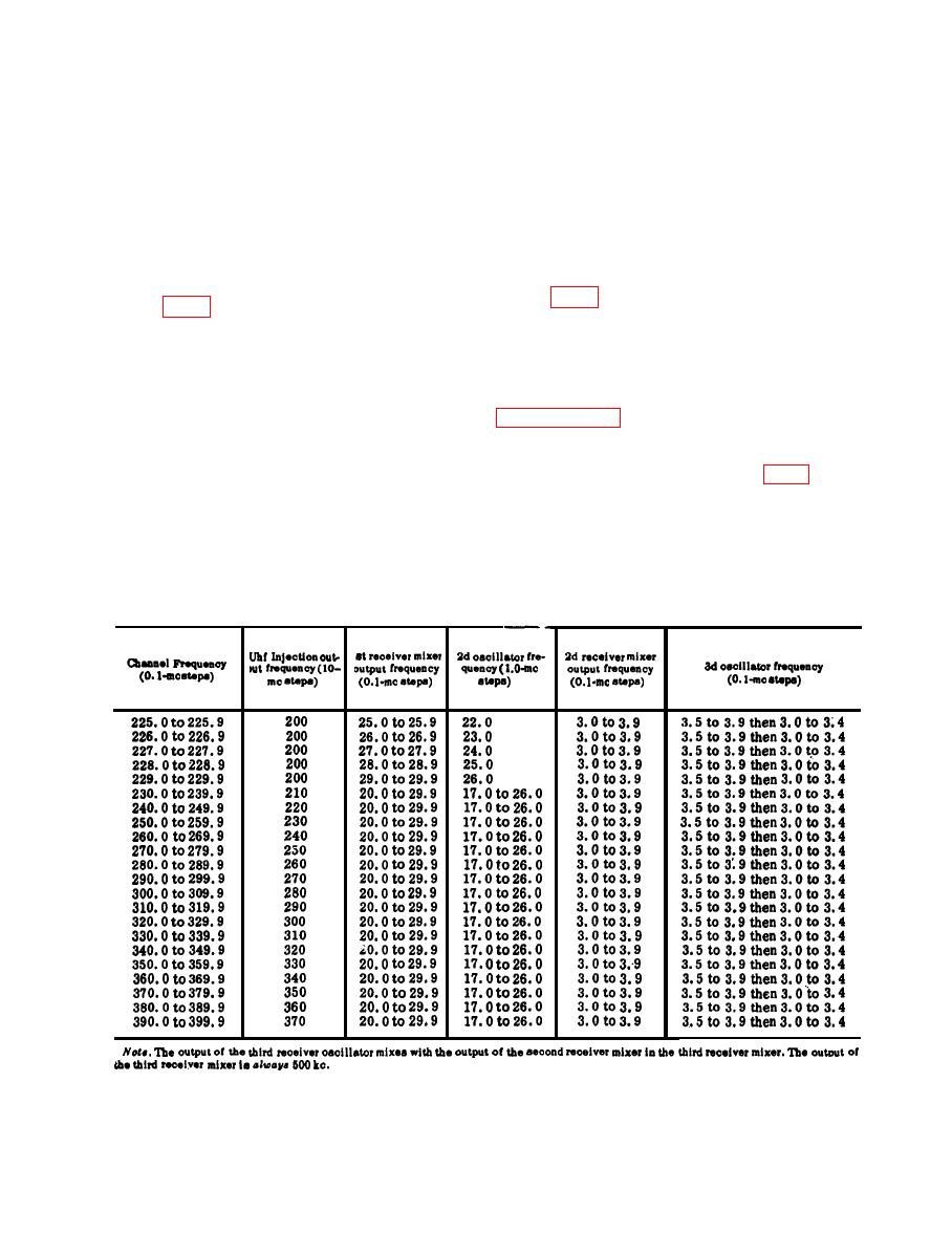
The following chart correlates the dial
from the +125-volt supply through voltage
settings with the oscillator and mixer
dropping resistor R210 and rf choke L226.
circuit frequencies. The chart applies to
the receive function.
Choke L226 and capacitor C219, decouple
|
|
Privacy Statement - Press Release - Copyright Information. - Contact Us |
