 |
|||
|
|
|||
|
Page Title:
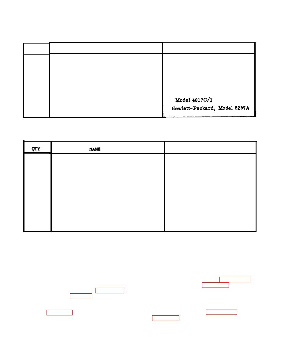
Table 3-1. Transponder Set Test Set AN/APM-378, Maintenance Test Equipment Required |
|
||
| ||||||||||
|
|  TM 11-4920-296-14&P
Maintenance Test Equipment Required
MIL TYPE No. /MFR & MODEL NO.
NAME
QTY
Weinschel 2-6
Attenuator, Fixed Coaxial 6 dB
1
Fluke, Model 8800A/AA
Digital Multimeter
1
Hewlett-Packard, Model 5245L
Electronic Counter
1
Tektronix 475-4
Oscilloscope, Dual Trace
1
General Microwave Corp. ,
Power Meter
1
T r a n s f e r Oscillator
1
Maintenance Test Equipment Required (Army)
MILITARY TYPE NUMER
1
Attenuator. Fixed 6dB
Weinschel 2-6
1
D i g i t a l Voltmeter
AN/GSM-64B
1
E l e c t r o n i c Counter
TD-1225(V)l/U
1
AN/USM-281A
1
Power Meter
AN/USM-161
1
Circulator
M3B-1030 ( 96341)
1
P u l s e Generator
AN/UPM-15A
chassis next to power transformer. Ref-
wiring of the test set. Therefore. when
erence is also made to E-terminals located
the trouble analysis diagram so indicates
on the motherboard. All E-terminals are
that the probable cause of the faulty indica-
e x p o s e d adjacent to the base of the plug-
tion is in wiring or power supply, check
in board housing.
those circuits by use of the schematic and
wiring diagrams, using normal voltage/
resistance measurement techniques.
3 - 1 4 . The flow diagrams of figure 3-2
and the procedures of table 3-3 refer to
video and rf problems. T e s t s are made
3-13. The flow diagrams of figure 3-1
on the underside of the rf housing by using
and the procedures of table 3-2 refer pri-
an extender cable (extender cable is not
marily to digital problems of the Ul, U2.
-
supplied; must be fabricated). See the cable
U3 and U4 plug-in modules. The test
fabrication drawings of figure 3-10. Refer
points in figure 3-1, which are preceded by
a 'U' number, refer to digital boards and
to figure 3-8 for the location of test points
are color coded. The other TP numbers
as indicated by the flow diagram of figure
3-2.
are power supply test points, located on
|
|
Privacy Statement - Press Release - Copyright Information. - Contact Us |
