 |
|||
|
|
|||
|
Page Title:
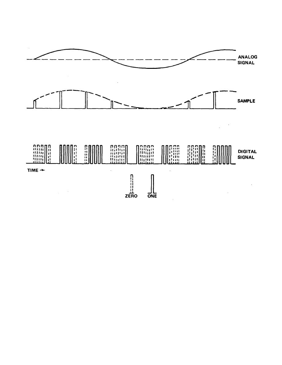
Figure 3-3. Conversion of analog to digital signals. |
|
||
| ||||||||||
|
|  TM 11-490-5
Figure 3-3. Conversion of analog to digital signals.
system to interference is a major factor in the error rate
(2) Since interference in a digital system causes
the system can tolerate without total loss of information
errors in the digital bit stream, some method of error
transfer.
detection can be used to monitor system 'performance.
(4) Since the interference does not appear directly
If adequate error correction cannot be provided,
in the audio channel output, the output will not provide
retransmission must be requested, either automatically
reliable information for interference identification.
or manually. In a voice channel these errors can cause
However, the total or composite signal is generally
a change in one or more words with little indication that
present in some form at the receiver detector.
interference is present. In a data channel, erroneous
Therefore, by monitoring this composite signal prior to
data is the result.
pulse detection and restoration. an appropriate display
(3) Most digital systems require some type of time
could be used to detect and identify interference in a
synchronization between the encoder at the transmitting
manner similar to that used in an analog system.
end and the decoder at the receiving end.
The
susceptibility of this synchronization
3-3
|
|
Privacy Statement - Press Release - Copyright Information. - Contact Us |
