 |
|||
|
|
|||
|
|
|||
| ||||||||||
|
|  TB 9-2320-387-35-5
NOTE
Remove terminal board cover before connecting leads, and
reinstall cover after leads are connected.
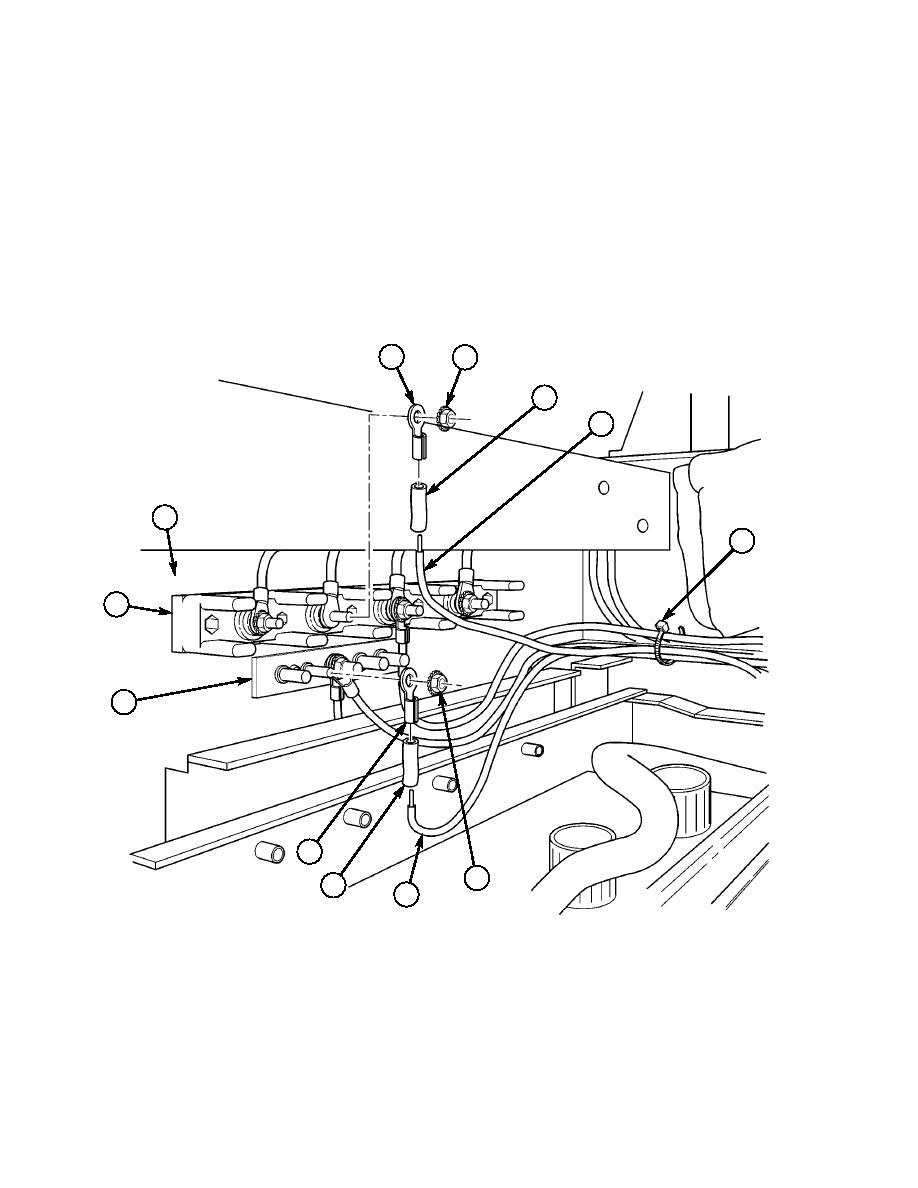
22-57. Attach heat shrink tubing (89) and two terminal lugs (86) and (92) to HF 20 watt radio power cable
negative lead (99) and HF 20 watt radio power cable positive lead (97). (Refer to TM 9-2320-387-24
for terminal connector repair.)
22-58. Connect HF 20 watt radio power cable positive lead (97) to 24-volt terminal board (94), located on
cab enclosure panel (95), with existing nut (96).
22-59. Connect HF 20 watt radio power cable negative lead (99) to ground strap (93), located on cab
enclosure panel (95), with existing nut (98). Secure all leads together with tiedown strap (32).
86
96
88
97
95
32
~
94
93
92
98
88
99
32.
TIEDOWN STRAP MS3367-1-0 QTY. A/R
86.
TERMINAL LUG 7728780 QTY. 1
88.
SHRINK TUBING MS23053/4-302-0 QTY. A/R
92.
TERMINAL LUG 7728777 QTY. 1
Figure 5-94.
5-69
|
|
Privacy Statement - Press Release - Copyright Information. - Contact Us |
