 |
|||
|
|
|||
|
Page Title:
Section XIX. EPLRS CABLES INSTALLATION |
|
||
| ||||||||||
|
|  TB 9-2320-280-35-3
Section XIX. EPLRS CABLES INSTALLATION
NOTE
Lay out all cables in their approximate positions before clamps are
installed. This will minimize cable length and ensure all slack is
taken out of all cables from front of vehicle to rear.
Excess slack in all cables will be stored under EPLRS mount
assembly.
This procedure applies to installation of EPLRS cables without
MTS installed. Installation of EPLRS cables with MTS is similar.
Loosen right-side tunnel insulation before performing step 19-1.
(Refer to TM 9-2320-280-20.)
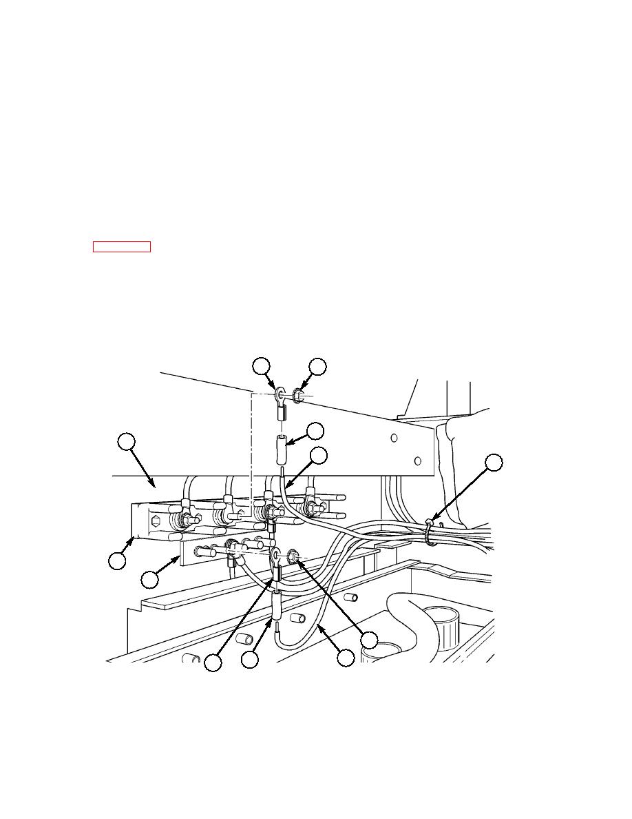
19-1. Route power cable (14) under right-side tunnel insulation towards terminal board. (Refer to
19-2. Attach shrink tubing (4) and two terminal lugs (2) and (8) to power cable negative lead (7) and
power cable positive lead (5). (Refer to TM 9-2320-280-20 for terminal connector repair.)
19-3. Connect power cable positive lead (5) to 24V terminal board (10) on cab enclosure panel (1) with
existing nut (3).
19-4. Connect power cable negative lead (7) to ground strap (9) on cab enclosure panel (1) with existing
nut (3). Secure all leads together with tiedown strap (6).
19-5. Secure right-side tunnel insulation. (Refer to TM 9-2320-280-20.)
2
3
4
1
5
6
~
10
9
3
7
4
8
2.
TERMINAL LUG 7728780 QTY. 1
4.
SHRINK TUBING MS23053/4-302-0 QTY. A/R
6.
TIEDOWN STRAP MS3367-1-0 QTY. A/R
8.
TERMINAL LUG 7728777 QTY. 1
Figure 5-58.
|
|
Privacy Statement - Press Release - Copyright Information. - Contact Us |
