 |
|||
|
|
|||
|
|
|||
| ||||||||||
|
|  TB 9-2320-280-35-13
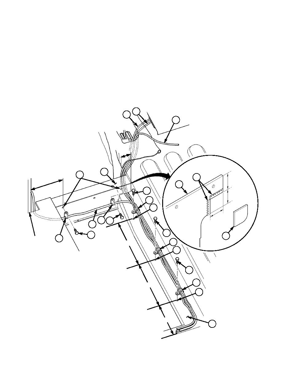
NOTE
Perform step 21-10 for vehicles with left rear cab enclosure panel
only.
21-10. Cut 2x2 in. section (32) from left rear cab enclosure panel (30). Install grommet (31). Reinstall cab
enclosure panel (30). (Refer to TM 9-2320-280-20.)
21-11. Locate, mark, and drill five 0.147-in. holes (23) along tunnel edge (27) and rear of left B-beam (24).
21-12. Route INC-EPUU cable (12), URO extension cable (18), and power cable (15) rearward under
B-beam (24) and along tunnel edge (27).
21-13. Route antenna cable (29) along rear of left B-beam (24) and secure with two loop clamps (28) and
self-tapping screws (25).
21-14. Route INC-EPUU cable (12), URO extension cable (18), power cable (15), and antenna cable (29)
rearward along tunnel edge (27) and secure with three clamps (26) and self-tapping screws (25).
15
12
18
2.00
24
23
31
5.50
30
25
2.00
26
23
0
2.0
28 25
29
25
25
32
28
B-PILLAR
26
0
11.0
23
25
26
0
11.0
23
25.
SELF-TAPPING SCREW 9421073 QTY. 5
26.
LOOP CLAMP MS21333-77 QTY. 3
8.00
28.
LOOP CLAMP MS21333-72 QTY. 2
27
31.
GROMMET MS21266-1N QTY. A/R
Figure 5-84.
5-64
|
|
Privacy Statement - Press Release - Copyright Information. - Contact Us |
