 |
|||
|
|
|||
|
|
|||
| ||||||||||
|
|  TB 9-2320-280-35-13
NOTE
It may be necessary to drill four 0.147-in. holes in right
wheelhouse/utility area before performing step 15-9.
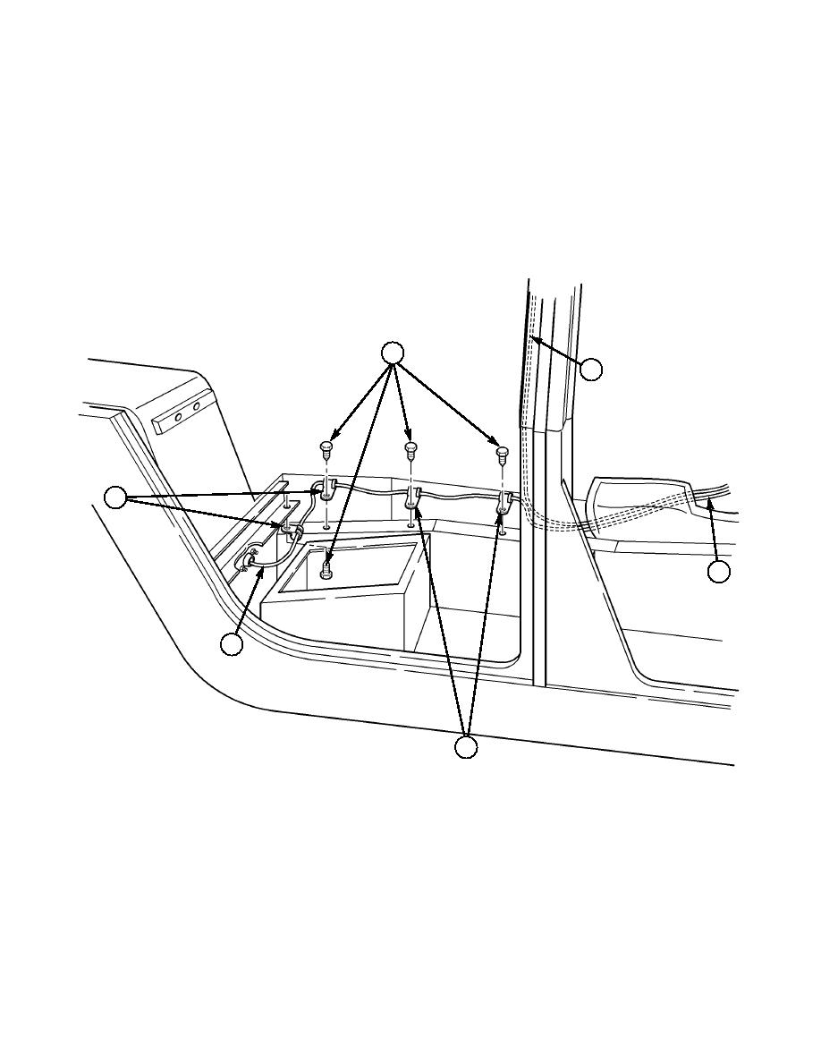
15-9. Route antenna cable (17) up B-beam. Secure with tape until antenna and cable are installed in
Section XXII.
15-10. Route antenna cable (6) along right rear seat/utility area with four self-tapping screws (20) and
loop clamps (21).
15-11. Route antenna cable (6) through right wheelhouse/utility area with existing grommet, retainer,
screws, and plain-assembled nuts. (Refer to TM 9-2320-280-20.)
20
17
21
6
6
21
20. SELF-TAPPING SCREW 9421073 QTY. 4
21. LOOP CLAMP MS21333-75 QTY. 4
Figure 5-57.
5-41
|
|
Privacy Statement - Press Release - Copyright Information. - Contact Us |
