 |
|||
|
|
|||
|
|
|||
| ||||||||||
|
|  TB 11-5820-890-10-9
Equipment Setup/Operation. Assemble and install the radio set and DMD individually per applicable
4.
technical manuals. Perform Preventive Maintenance Checks and Services (PMCS) and/or Built-In-Test
(BIT) functions. Load all frequencies, hopsets, and variables into the radio set and establish voice
communications before connecting the DMD to the radio set. Once voice communication has been
established, connect the DMD as described in the following paragraph.
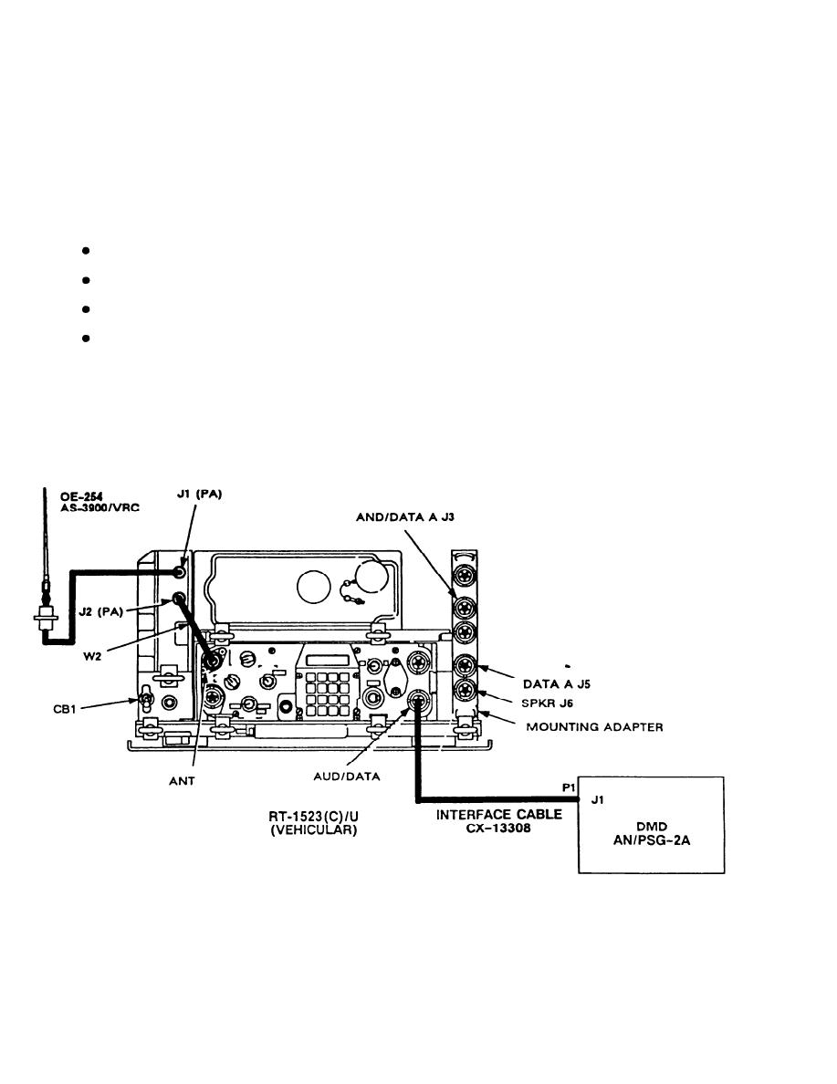
Cabling Instructions. The following figure illustrates the typical configuration for the connection between
5.
the radio set and the DMD.
Connect interface cable CX-13308 from DMD J1 connector to RT AUD/DATA connector.
Connect handset H-250/U to RT AUD/FILL connector.
Figure shows DMD connected to lower radio (RT-A).
DMD may be connected to upper radio (RT-B) if desired.
NOTE
The interface cable CX-13308 must be used. It is identified in the SINCGARS AAL as
National Stock Number 5995-01-303-0308. This cable replaces the existing DMD FSK
cable.
Figure 1. Cabling for DMD to SINCGARS Radio Set
2
|
|
Privacy Statement - Press Release - Copyright Information. - Contact Us |
