 |
|||
|
|
|||
|
Page Title:
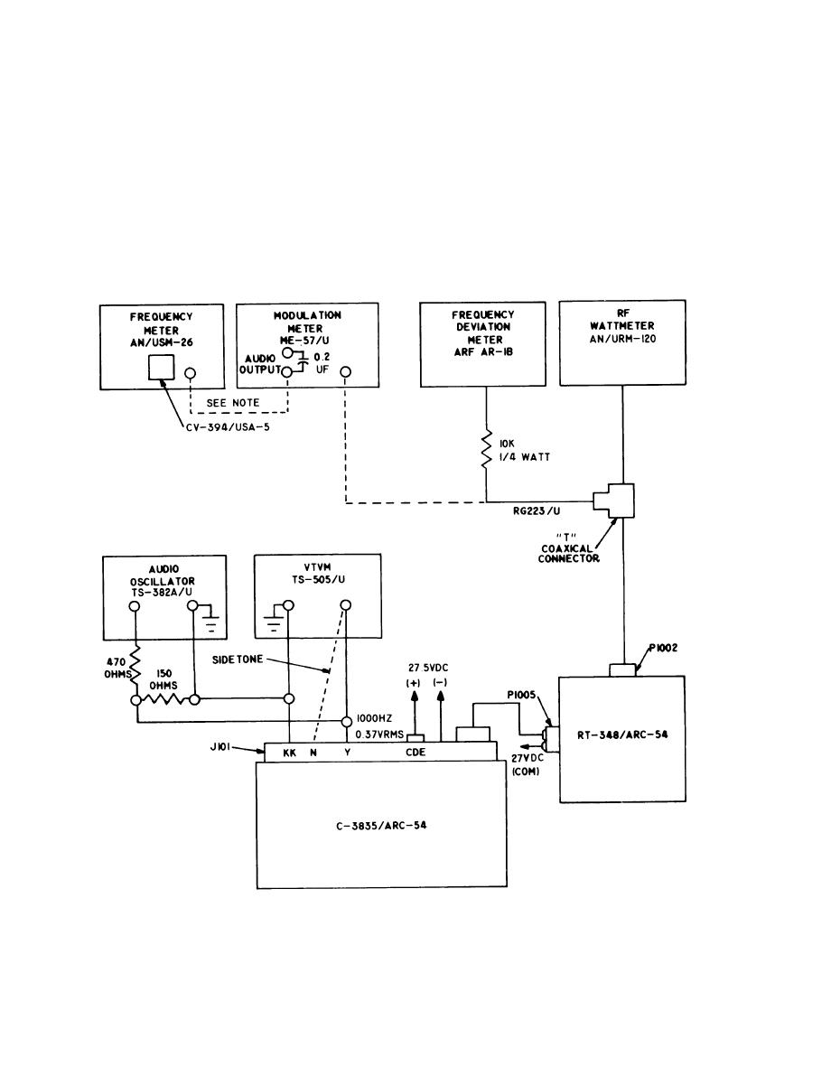
Figure 1. Transmitter test setup. |
|
||
| ||||||||||
|
|  aligned, proper left-right deflection will
tions is not obtained after adjustments
now be possible.
of R224 and R227, it may be necessary
to adjust coils L-204 and L-205. The coils
6. With each adjustable attenuator set
should be peaked at 50.00 MHz. A fre-
for 6 db each, set the signal generator output to
quency counter such as the CP-772/U
2000 microvolt. When using the ID-1351A, the
with plug-in unit CV2002/U or equiv-
horizontal pointer (signal strength indicator) on
alent should be used to make sure that
the left side of the ID135/A should be centered
on the first dot below the rest position of the
When these coils are peaked, resistors
pointer. If a microamp meter is used, the reading
R224 and R227 may have to be re-
shall be 37.5 microamps plus or minus 20 micro-
amps. If the above indication or microamp read-
adjusted. If the RF and IF sections of
ing cannot be obtained, adjust R211 on the
are properly
the AN/ARC-54( )
NOTE:
CONNECTION OF MODULATION METER,
FREQUENCY METER AND 0.2UF CAPACITOR
EL740-5821-91-004-SB-I
IS FOR TONE DEVIATION TEST
Figure 1. Transmitter test set u p .
12
|
|
Privacy Statement - Press Release - Copyright Information. - Contact Us |
